In![]() struction for CAD Electronic Catalog << Return to CAD System
struction for CAD Electronic Catalog << Return to CAD System
|
Drawing creation method |
Drawing
creation method (Combination of the data)
1- How to create the SY5000 body-ported-type solenoid valve (single
unit) data.
Step 1:
Decompose the child drawings
Step 2: Select the pivot (base
point) specifying the target drawing
Step 3: Paste the bracket assembly
to the valve body
Step 4: Paste the port block
assembly to the valve body
2- How to modify the stroke of the cylinder (CQ2) (Stretch)
Step 1: Decompose the child
drawings (CQ2: DIA.50)
Step 2: Choose the stretch command
Step 3: Specify the stretch line
Step 5: Specify the moving
distance (Stroke)
3- How to create
the body-ported manifold, bar stock type / Individual wiring
Step 2: Paste the port block to the single valve unit
Step 3: Paste the manual to the valve
Step 4: Preparation of the manifold base
Step 5: Paste the solenoid valve to the base (Station 1)
Step 6: Paste the solenoid valve to the base (After Station 2)
<<
Return to CAD System <
Return to INDEX
1- How to create the SY5000 body-ported-type solenoid valve (single unit)
data.
(When combining 2 types of files)
Some child drawings in the file have their own
number.
The following are examples of product data
produced from 2 files.
|
File name |
SY5000-G |
SY5000-OPTION |
|
#1 (Child drawing No.) |
SY51*0-*G (SINGLE SOLENOID
VALVE) |
SY5000-27-1 (SUB-PLATE) |
|
#2 |
SY52*0-*G
(DOUBLE SOLENOID VALVE) |
SX5000-16-2A (BRACKET ASSEMBLY) |
|
#3 |
SY5**0-*G (3
POSITION SOLENOID VALVE) |
SX5000-16-1A (BRACKET ASSEMBLY) |
|
#4 |
--- |
SY5000-6A-01* (PORT BLOCK ASSEMBLY) |
|
#5 |
--- |
SY5000-6A-C4/N3 (PORT BLOCK ASSEMBLY) |
|
#6 |
--- |
SY5000-6A-C6/N7 (PORT BLOCK ASSEMBLY) |
|
#7 |
--- |
SY5000-6A-C8/N9 (PORT BLOCK ASSEMBLY) |
|
#8 |
--- |
ARBY5000-M1-*-2 (INTERFACE REGULATOR) |
|
#9 |
--- |
ARBY5000-00-*-2 (INTERFACE REGULATOR) |
In order to create the solenoid valve body ported type (SY5220-5G-C6-F1)
data using the AutoCAD,
File name: SY5000-G, #2 and
File name: SY5000-OPTION, #2/#6
will be required.
<<
Return to CAD System < Return to INDEX
Step 1:
Decompose the child drawings
For data that will be created from only one
file, a copy and paste process can be executed using only the child drawing
Number.
However, when two or more files are necessary to
make a data, the file to be copied must be decomposed
(ungroup the data) so that there will be no
overlapping No.
(e.g.: If SY5000-OPTION is pasted to SY5000-G
without decomposition, #1, #2 and #3 cannot be pasted.)
For the actual operation, choose the target and
execute the AutoCAD command [Modify] Þ [Decompose].

#2
(F1: Foot bracket)
#6
(DIA.6
One-touch fitting)
File name
SY5000-OPTION
<<
Return to CAD System < Return to INDEX
Step 2: Select the pivot (base point) specifying the target drawing
After ungrouping SY5000-OPTION #2 and #6, paste
them to SY5000-G.
Select all parts of the outline drawing of #2 and
execute the AutoCAD command [Edit] Þ [Pivot Copy].
 Then select the pivot (base
point).
Then select the pivot (base
point).
![]() This is an enlargement of the bottom view
shown below.
This is an enlargement of the bottom view
shown below.
The PIVOT
(base point) is marked with O in the drawing.
Here are all the parts of the outline drawing of
#2 (bracket) to be pasted to the valve.
(Top
view)
(Front view)
(Right side view)
(Bottom
view)
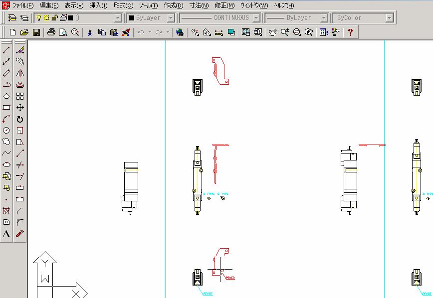
The following are all of the contents of SY5000-G
to which SY5000-OPTION #2 is to be pasted.
As it is a double solenoid type that is selected
here, paste the bracket to SY5000-G #2.
<<
Return to CAD System < Return to INDEX
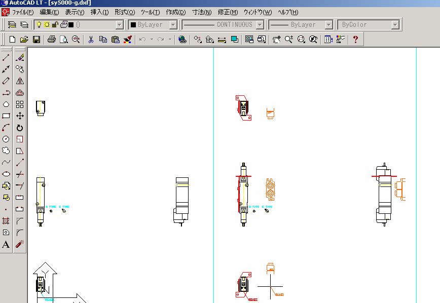
Step 3: Paste the bracket
assembly to the valve body
The figure below shows the stage just before
pasting the 4-side views of the brackets
(colored in red here for clarification) to
SY5000-G #2 (double solenoid).
Simply by combining the bracket PIVOT to the
valve PIVOT, all 4 sides can be pasted.
SY5000-G (#2)
<<
Return to CAD System < Return to INDEX
Step 4: Paste the port block Assembly
to the valve body
By performing the same operation described
above, the port block can be pasted to the valve body.
The figure below shows the process of pasting
the port block Assembly (colored in orange here for clarification) to the valve
body.
<<
Return to CAD System < Return to INDEX
Step 5:
Completed
CAD data of the body ported type
(part No.: SY5220-5G-C6-F1) is completed when all of the operations described above have been
performed.
If necessary, the data of manual (operation) part
that is placed on the right side of the valve body drawing can be pasted to the
body.

<<
Return to CAD System < Return to INDEX
1- How to
modify the stroke of the cylinder (CQ2)
The data of actuators such as cylinders is
generated for a specific stroke due to the data organization.
In order to modify
this original stroke data, the overall length must be changed according to the
stroke table placed on the left side of the cylinder drawing.
(The initial stroke of the data is marked with O on the left side of the stroke table.)
<<
Return to CAD System < Return to INDEX
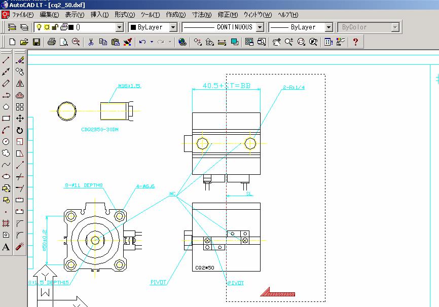
Step 1:
Decompose the child drawings (CQ2: DIA.50)
The data for each cylinder is grouped together
(in the form of child drawings).
In order to modify the stroke, the data must be decomposed
(ungrouped).
For actual operation, choose the target and
execute the AutoCAD command [Modify] Þ [Decompose].
Also, when the auto switch is used, it should be
decomposed because the auto switch part is grouped by itself.

<<
Return to CAD System <
Return to INDEX
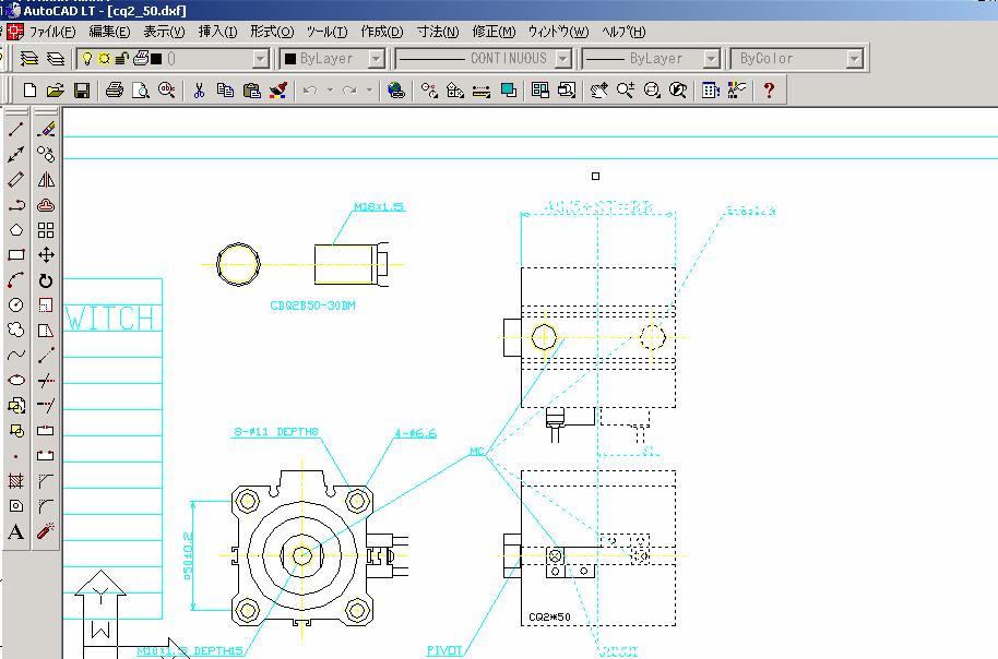
Step 2:
Choose the stretch command
Select the AutoCAD command [Modify] Þ
[Stretch].
After selecting the command, specify a range
that covers from the right side of the cylinder to the SL
(stretch line).
(Stretch cannot be executed from the left side
of the cylinder. Select the range from the direction indicated by the arrow in
the figure below.)
<<
Return to CAD System < Return to INDEX
Step 3: Specify
the stretch line
After specifying the range, press the linefeed
Enter key.
<<
Return to CAD System < Return to INDEX
Decide the base point for the stretch.
The endpoint will be defined as this base point.
<<
Return to CAD System < Return to INDEX
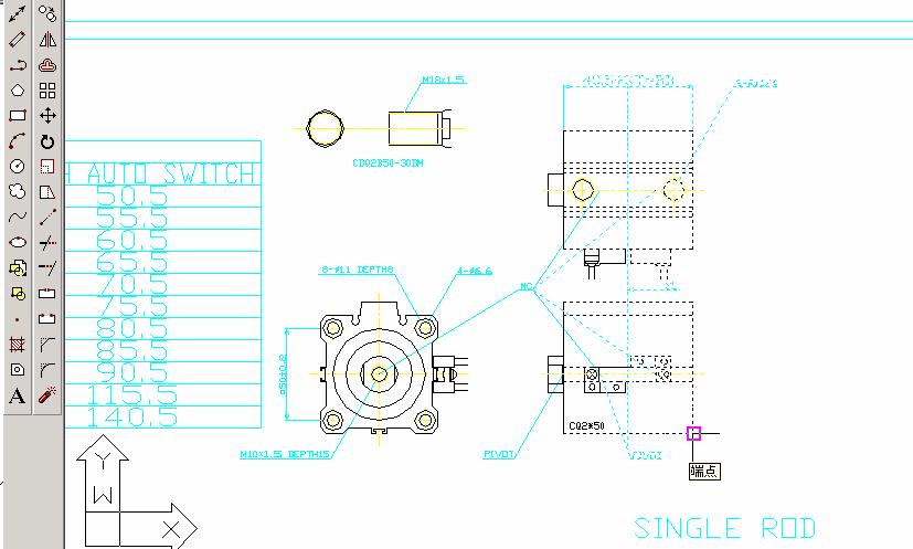
Step 5:
Specify the moving distance (Stroke)
Specify the moving distance of the stroke.
The initial stroke of the cylinder is 30 mm
(Marked with “O” in the
table below).
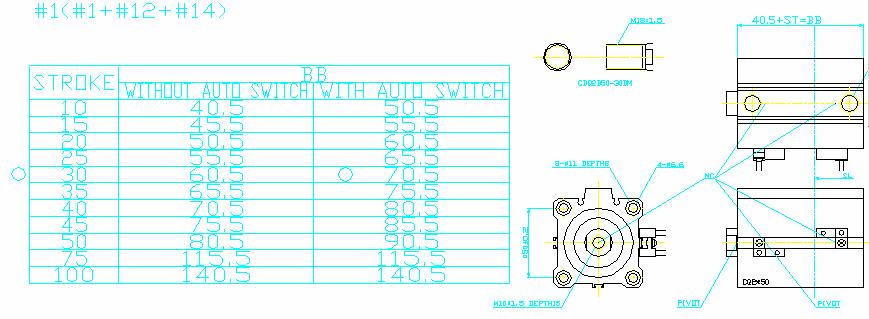
In order to change it to 50 mm, it must be moved
by a distance of 80.5 - 60.5=20[mm] in the direction of the X-axis so that the
BB dimension will be 80.5.
(Movement in the direction of the Y-axis is 0 as
it is not necessary.)
Thus, enter @20, 0 (X-axis moving distance),
(Y-axis moving distance)
By pressing the linefeed Enter key, the command
will be executed and the cylinder stroke will be extended by 20 mm.
After the
modification (Stroke: 50mm)
<<
Return to CAD System < Return to INDEX
3- How to create the body-ported
manifold, bar stock type / Individual wiring
Part numbers
SS5Y3-20-08 (Type 20, 8 station manifold base)
 * SY3220-5GSE-C4 (4 valves)
* SY3120-5GSE-C4 (4 valves)
Step 1: Download the 3
files.
The
filenames for the SY3000 Series are
1) SS5Y3-20_20P (The file for the manifold base)
2) SY3000-G (The file for the valve)
3) SY3000-OPTION (The file for options such as the body-ported type)
Usually, the file is named after the
relevant product part number.
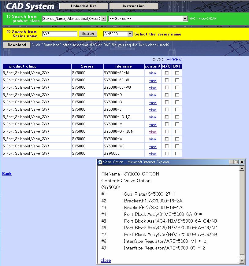
Click the view button in the content field to
see the specific child drawing numbers.
The figure below shows
the screen that appears when the view button is clicked.
<<
Return to CAD System < Return to INDEX
Step 2: Paste
the port block to the single valve unit
The valve mounted on the manifold base is
completed with the files below.
2) SY3000-G (The file for the valve)
3) SY3000-OPTION (The file for options such as the body-ported type)
First, open the file SY3000-OPTION. The file
to be copied must be decomposed (ungroup the data) so that there will be no
overlapping with the child drawing number.
Second, select the drawing data that shows all 4
sides of the body-ported port block SY3000-6A-C4/N3 (#5) and copy the pivot as
the base point.
Refer to section 1-Step 2 for the base point
(pivot) copy method.
Third, simply by combining the port block pivot
to the valve pivot, #5 can be pasted to #1(SY31*0-*G: Single solenoid) and
#2(SY32*0-*G: Double solenoid) in file No. SY3000-G.
The left drawing below shows the stage after the
port block has been pasted (colored in blue here for clarification) to the
single solenoid and the right drawing shows the stage just before the port
block will be pasted to the double solenoid.
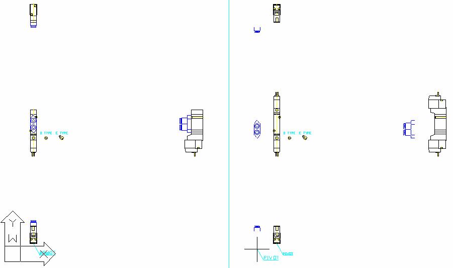
Single Solenoid Valve
Double Solenoid Valve
(SY31*0-*G) (SY32*0-*G)
<<
Return to CAD System < Return to INDEX
Step 3: Paste
the manual to the valve
 Mount the manual override
(manual operation button) to the data created by Step 2. (Front view)
Mount the manual override
(manual operation button) to the data created by Step 2. (Front view)
Since each solenoid child drawing is grouped
with a manual override,
the data must be decomposed (ungroup the data).
Since this manual override is the push-turn
locking lever style, move the manual override on the right side of the solenoid
to
the specified position. (Delete unnecessary data
if required.)
<<
Return to CAD System < Return to INDEX
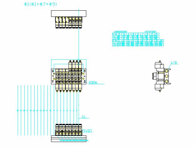
Step 4:
Preparation of the manifold base
Filename: SS5Y3-20_20P (The file
for the manifold)
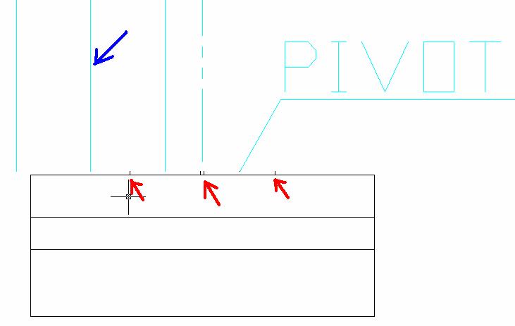
On the manifold base, there are some sections
that come in contact with the valves (see the sections indicated by the
red arrow).
Therefore, before stretching the manifold base,
copy the contact sections and paste the numbers you need onto the drawing based
on the number of valve stations using the pivot copy method.
Since the lines indicating the valve mounting
position shown in #9 is unnecessary for stretching the manifold base, delete
this child drawing and paste it using the pivot copy method after stretching.
(Note: #9 can be deleted all at once after #1 has been decomposed.)
The drawing below is a diagram of the manifold
base after preparation and before mounting the valves.
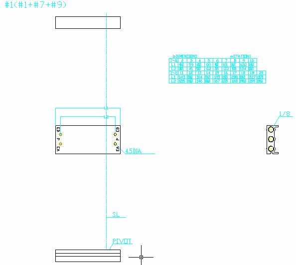
The drawing below is an enlargement of the
manifold base.
The manifold base length was changed to agree
with the number of valve stations before mounting the valves.
 (This is the manifold base with
8 stations.)
(This is the manifold base with
8 stations.)
Filename: SS5Y3-20_20P
(The file for the manifold)
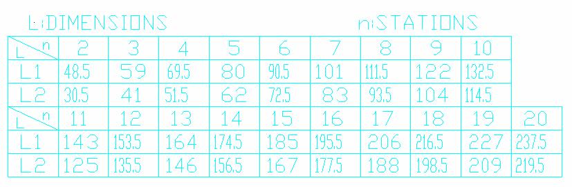
Each manifold base has a station table. Change
the length in accordance with the table.
The data at default is for 2 stations.
The data for 8 stations are
Moving distance L1=111.5 –
48.5 Moving distance of L2
=93.5 – 30.5
(8 stations) (2 stations)
(8 stations) (2 stations)
Stretch L1 to the X axis –63 and stretch L2 to
the X axis –52.5 to complete the 8-station manifold base.
(Redraw the lines after stretching.)
Execute the decompose command in the same manner
described in section 1.
Refer to “how to modify the stroke of the
cylinder (stretch)” for the stretching method.
<<
Return to CAD System < Return to INDEX
Step 5: Paste
the solenoid valve to the base (Station 1)
For pasting the Station 1 solenoid valve to the
manifold base, select the valve drawing showing all 4 sides and copy it by
copying the pivot point (base point).
The valve can be mounted by pasting the drawing
to the pivot of the manifold base.
The data below shows the configuration after the
Station 1 valve is mounted.
<<
Return to CAD System < Return to INDEX
Step 6: Paste the
solenoid valve to the base (After Station 2)
For the data after the Station 2, select the
drawing data that excludes the side view but includes the other 3 sides and
copy the data by copying the pivot point (base point).
Since the section between the valve and the base
that is in contact becomes the pivot of Station 2, place the valve here.
The data below shows the configuration after
Station 2 is mounted.
The data below shows an enlargement of the pivot
and stations.
(Usually, the indication of the PIVOT point does
not need to be copied, but it is shown to mark its position.)
STATION
(10, 9, 8. . .)
<<
Return to CAD System < Return to INDEX
The data below is completed by mounting 4 double
solenoid valves and 4 single solenoid valves.
Part Number SS5Y3-20-08 (Type 20, 8
station manifold base)
*SY3220-5GSE-C4 (Mounted valve x 4 stations)
*SY3120-5GSE-C4 (Mounted valve x 4 stations)
<<
Return to CAD System < Return to INDEX
©2005 SMC
Corporation all rights reserved.